Original: VoicelessComm.doc 11/18/97
The worst-ever aviation tragedy was two 747’s that collided on the ground in the Canary Islands. It was caused by a communications failure.
A great improvement in aviation safety would arise from reducing or eliminating problems associated with voice communication. This proposal describes such a system.

Aftermath of the worst disaster in aviation history
It would eliminate most voice communications in commercial aviation and in time, general aviation as well. For this article, we’ll call the equipment “DiComm” for digital communications.
Basic Idea
Controller instructions are given by using a touch-sensitive console. Pilots get instructions on a special display, with an alert, that lets them accept or reject. Once accepted, the controller’s display updates accordingly, much like the readback method currently in use only vastly faster and more reliable.
Voice communications are maintained by the pilot checking in on a new frequency. This allows for emergencies, unusual instructions, pilot requests, weather avoidance, and for aircraft that do not have the necessary equipment.
The automation logic would be programmed to reduce workload by the controller and increase clarity for the pilot. Other aspects of the automation (such as having it know what the aircraft has been instructed to do) will further enhance safety since predictive warnings could be generated from obviously faulty instructions even before those instructions are sent to the aircraft.
-
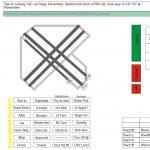
- Tower controller proposed touchscreen interface
-

- Approach controller proposed touchscreen interface
Most instructions could be handled this way during normal and near-normal operations. In bad weather, things will have to slow down (as they do now) to accommodate increased workload and weather deviations. The system does allow for significant variance in each controller’s method of operation since the scratch pads can be set to whatever the controller wants.
Aircraft Equipment
The aircraft equipment is comprised of the data-link transceiver, Pilot Response Unit on the center console (within reach of both pilots), and an Instruction Display viewable by both pilots.
The Pilot Response Unit has the following elements:
 Accept/Reject/Execute button. When an instruction is received on the Instruction Display the pilot not flying (PNF) pushes the appropriate button. Normally, as with voice communication, it will be “Accept” which is just like the current readback of the instruction. A readback is not required since the equipment does validity checks on its own and the instruction remains on the display for the pilot to review if there is confusion. Reject would be used for those rare cases where the instruction is something that would not work well such as a turn into weather or climb above the aircraft’s current capability. When that happens, a voice communication would be expected from the pilot so the situation could be resolved.There is a computer-generated voice that “reads” the instructions as they are received out loud so the pilots don’t have to be looking at a display. A volume control on the unit allows this voice to be adjusted all the way to off. There is a separate volume control for the instructions sent to other aircraft that also may be adjusted to off if desired.
If the controller adds emphasis (double-clicking his exclamation mark) the PRU sounds a chirp indicating immediate action is required. This is because the system obviously will not transfer what would be controller voice inflections. In an emergency, whenever it would be faster to do so, the controller would simply key his microphone and use voice.
- Instruction Display (ID). This consists of two display sections, a brightness control, and a recall button. The main display is in a larger font and contains the instructions for this aircraft. As new instructions come up the old ones scroll down and then disappear. The value is that the old instructions can be viewed. It would actually store the most recent 10 instructions which could be recalled by pressing the recall button. After a brief display the ID would return to its previous state showing the most recent instruction.The secondary display section is in a smaller font and contains instructions to other aircraft. It also scrolls so that the most recent instructions to other aircraft can be viewed. This allows the pilots to maintain some awareness of what is happening with other aircraft under the controller’s jurisdiction.
Transmission
Voice communications is maintained on the existing VHF system. Pilots check in with voice in the same manner they do now. A method for preventing blocked transmissions, data or voice, should be implemented in both the aircraft and ground stations. This would make sure there was no carrier present on the frequency before transmitting. For voice, the transmitter would simply not operate and the person trying to transmit would hear the existing signal. For data, if there was a carrier present, the carrier signal would be received and the transmission made as soon as the frequency was clear.
Here are three possible methods of implementing the data-link. The first one is probably un-workable but is mentioned for completeness. The second is probably very workable and is the least expensive and the third is the most desirable.
All methods would incorporate error detection common in digital data transmission such as checksum or CRC. This way a transmission could be validated. For example, an instruction is sent by approach control (ATC). The aircraft equipment receives it, calculates a checksum, and replies immediately with that checksum. When the ATC equipment receives the proper checksum then the transmission process is complete. If this did not take place then the controller would get back a message saying the instruction was scrambled and he needs to re-send it. The equipment could make a couple of tries before reporting this to the controller. None of this is visible to the user unless an error occurs in transmission and then only the sender is alerted.
Method 1:
The data-link uses the aircraft’s mode-s transponder. The advantage is that some of the equipment (the transponder) is already installed in the aircraft. There are, however, several limits that would have to be overcome. It would not work if the controller’s instruction has to wait until the radar antenna is pointed at the aircraft Then the pilot’s reply would have to wait until the antenna is pointed at the aircraft again. This could very easily be up to 5 seconds from when the instruction was given or reply made.
Another problem is that other pilots would not receive instructions to all aircraft. This would reduce situational awareness which helps a pilot know what’s going on around him.
This method may not work well on the ground since it would require that the transponders be turned on. Having that many transponders on within a mile or two of the antenna may cause problems.
Method 2:
This would use the existing comm radios. Data would be transmitted and received on the same frequencies as the voice communications. There would be a problem with hearing the digital exchanges while listening on voice. They would sound like a fax machine or modem which would be an un-acceptable distraction to both pilots and controllers. A possible solution is to start each data communication with an in-audible tone such as 20Khz. Aircraft and ATC facilities would have a device just after the antenna that would be listening for this tone. When detected it would not send the signal to the comm receivers but instead route it to the DiComm equipment.
This would require some method of channelizing the antenna unit so that it would know which frequeny it was “listening” to. There should be blocked frequency protections to prevent transmission on the frequency is in use.
Method 3:
Probably the best method, this would allow the existing radios and frequencies to be used as they currently are and require new frequencies to be allocated for the data-link. The new ones would be channelized in parallel with the existing comm frequencies so that each comm frequency has a related data-link frequency. This is similar to the way DME is done.
Ground Equipment
There are different requirements for each type of ATC control facility: ARTCC (Air Route Traffic Control Center), TRACON (Terminal Radar CONtrol) and local/ground (towers) including clearance delivery. In addition to the required radio equipment (according to the method used) for the datalink, the controllers would have an additional touch-screen console at each station. This console is what would be used to issue commands and view pilot responses. All existing displays and controls would be left intact until some of these functions could be integrated.
Controllers Console
The console would be different according to the type of ATC facility and position its being used by. The one for a tower controller will be different than for a ground controller which is different than the clearance delivery position and so on.
They will have many things in common and, to the extent possible, similar information will be contained in the same general area between all units. This will facilitate controllers moving from one position to another.
There would have to be some linkage to the existing ATC computer system. The console needs to know the altimeter setting for the airports being worked, the surface winds for each airport, aircraft hand-off information, flight plans for the clearance position, and other data passed through as appropriate
Ideally, the system would work with the radar display and maybe in the future this could take place. Aircraft that have been issued instructions but not acknowledged them would appear blue until the pilot responded at which time they would return to white. Using this system would also give the capability to alert a controller when an instruction might put aircraft in conflict…either with another aircraft or terrain.
Sample Flight
To illustrate how the system would work under normal use an airline flight will be described giving details on the interaction between the controller and the pilot using the DiComm equipment. The example flight is Southwest (WN) 243 from Chicago’s MDW airport to Nashville’s BNA airport. The intent of this is to show how some of the minute details work in the system.
The Flight Plan and Clearance
Information presented in Arial pertains to the aircraft and its responses.
The company flight plan is sent using the current means to ATC. The strip prints in the same manner that does now. The data is also sent to the ATC DiComm computer.
The system knows the flight number which is entered only once per flight. He enters “C B C16” in the PRU data window and pushes send. “C” means the pilot is asking for a “Clearance”, they have information “B” and are parked at gate C16.
The DiComm console at the clearance delivery position chimes and “WN243” appears in the upper left corner flashing to indicate an aircraft wanting clearance. He double-clicks the flashing aircraft and it moves down to an open position in the aircraft list. The computer’s estimated clearance also comes up in the instruction window. If the controller needs to modify the clearance then he uses the keys on the console to do so. He pushes the SEND button when it’s correct. Upon doing so the aircraft in the list turns yellow (from white).
The aircraft hears a chime, sees the clearance up on the Instruction Display, the Accept, Execute, and Reject buttons light up, and if the volume is turned up the automated voice reads the clearance. If it is acceptable to the pilot he pushes Accept.
The aircraft number on the controller’s console turns to white indicating the pilot has accepted the clearance. The controller now presses the aircraft’s button, followed by the handoff button then the desired handoff position (lower right-hand corner…ground control in this case) and the aircraft turns blue to indicate a handoff has been initiated.
The receiving ground controller hears a chime (which can be turned down or off) and sees the aircraft flashing in the upper left corner. He double-clicks the aircraft or empty position on the list and the handoff is accepted. The aircraft’s list entry disappears from the clearance position’s display, stops flashing, and moves down to an open space in the flight list.
When ready, the pilot pushes “P” followed by SEND indicating he is ready to push back.
The ground controller hears a chime, sees the flight flashing and the letter “P” appears in the pilot request line. He selects an instruction, let’s say “cleared to push” and then SEND. If there is a delay he can use “stand by” or any of the other pre-programmed instructions (he can program them himself into the scratch pad). If there is something unusual then he will use voice. But since the vast majority of instructions are routine such as “you’re cleared to push after traffic passes behind” this will be required only occasionally. After pushing SEND, the flight number on the list turns yellow until the pilot acknowledges it. If the pilot were to deny the request (push REJECT) the aircraft number would flash yellow to alert the controller that voice clarification is required.
The aircraft hears a chime, sees “Cleared to push” on the Instruction Display, pushes the now-illuminated Accept button and proceeds with the push-back.
This process repeats through all phases of flight.
About the diagrams
These are conceptual in nature. There would be modifications as would be expected but they should suffice to convey the general idea.
Development Proposal
One idea to test this system relatively inexpensively is to develop the software for the DiComm console on a pen-based computer system and try it out in an ATC lab either at the FAA facility or a university equipped with one. The aspect that will likely prove the most challenging (from a human factors viewpoint) is the controllers console and interaction with the system. This needs to be proven first.
Conclusion
As a commercial pilot I want to see this implemented. It would improve safety probably as much as GPWS or other worthwhile safety ideas. This may save more lives per dollar than other safety innovations that have helped bring about our enviable aviation safety record.
In 1997 This was sent to several organizations including the FAA, Air Safety Institute, NTSB, SWA Safety Committee, and the ALPA ATC Committee.